Tech Stuff


Don't Use KV

Motor vendors have taken to characterizing their motors using the parameter KV. It has units of angular speed per volt, specifically RPM/volt. The notion is you drive an unloaded motor with a controller being sourced with some fixed voltage V. Then you measure the resulting speed of the motor. Then you form the ratio of RPM/V to form the constant KV. For the most part, a motor's RPM should rise linearly with input voltage.

There's another very similar motor quantity called Ke - the motor back-emf constant. It has units of volts per angular speed (actually Volt/radian/s). Ke should be the exact reciprocal of KV (using consistent units like MKS). But too often, it's not. Here's the problem.

To measure KV you drive your motor with some electronics. But the control methods are not specified. Is it 6-step square, 3-phase sine with field-oriented-control, is it operating with flux-weakening? The same input voltage to the same motor can yield completely different measured output speeds depending on the electronics. Also, the motor is supposed to be unloaded, but the bearings may have a lot of friction and there can be high iron corelosses. Both of those drag sources can vary non-linearly with speed thus messing up the KV calulation at higher speeds.

By contrast, Ke is measured open loop. You physically spin the motor and measure the generated output voltages and directly form output V per input angular speed. It is not affected by high currents, high corelosses, or high friction. It is a direct measure of the motor magnetics.

Ask for Ke. You can't trust KV.

kt=ke

Vibrations in BLDC motors

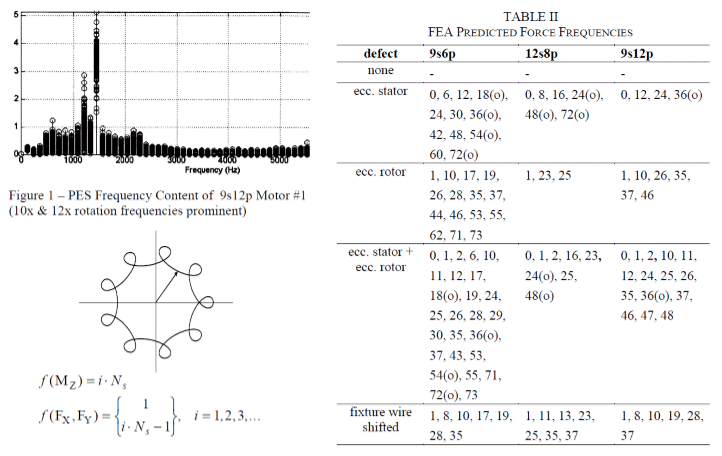
A noticeable characteristic of strong BLDC motors (especially NdBFe ones) is the vibration created as the rotating magnet poles pass by stator steel teeth. These pole / tooth interactions combine to make predictable vibrating forces. When a machine is perfectly made, it has a known set of cogging & shaking frequencies. When it’s made inaccurately or with defective magnets, it has a different set of defect frequencies.

Inspecting assemblies for problems is nearly impossible, since motors are very compact and tightly assembled. The best way to diagnose and solve a vibration issue is to measure running vibrations, compare measurements to FEA-derived frequency signatures, and deduce which component, tolerance, or process is the likely cause.

Although cogging torque was a big problem in the past, it is now well-understood. Cogging can be controlled by numerous techniques that have minimal effect on output.

kt=ke

Optimizing Machine Dimensions

A great way to design an EM device is to build a computer finite element model using dimensions as driving parameters (actually dimension ratios). Apply constraints like maximum size envelope, minimum clearances, electrical power limit, etc. Select a performance metric, and deploy a goal-seeking program to search for the best dimensions.

An optimization model is tricky to set up. It must be detailed enough to accurately model the physics, yet sufficiently robust to avoid degenerate geometry, mesh and convergence failures as the optimizer navigates the design space. When it works, however, optimization is like magic. The highest performing design often defies the designers’ intuition, and is usually the most efficient.

Our optimization approach is very general and works on motors, generators, actuators, etc.

kt=ke

Kt=Ke, Except When It Doesn't

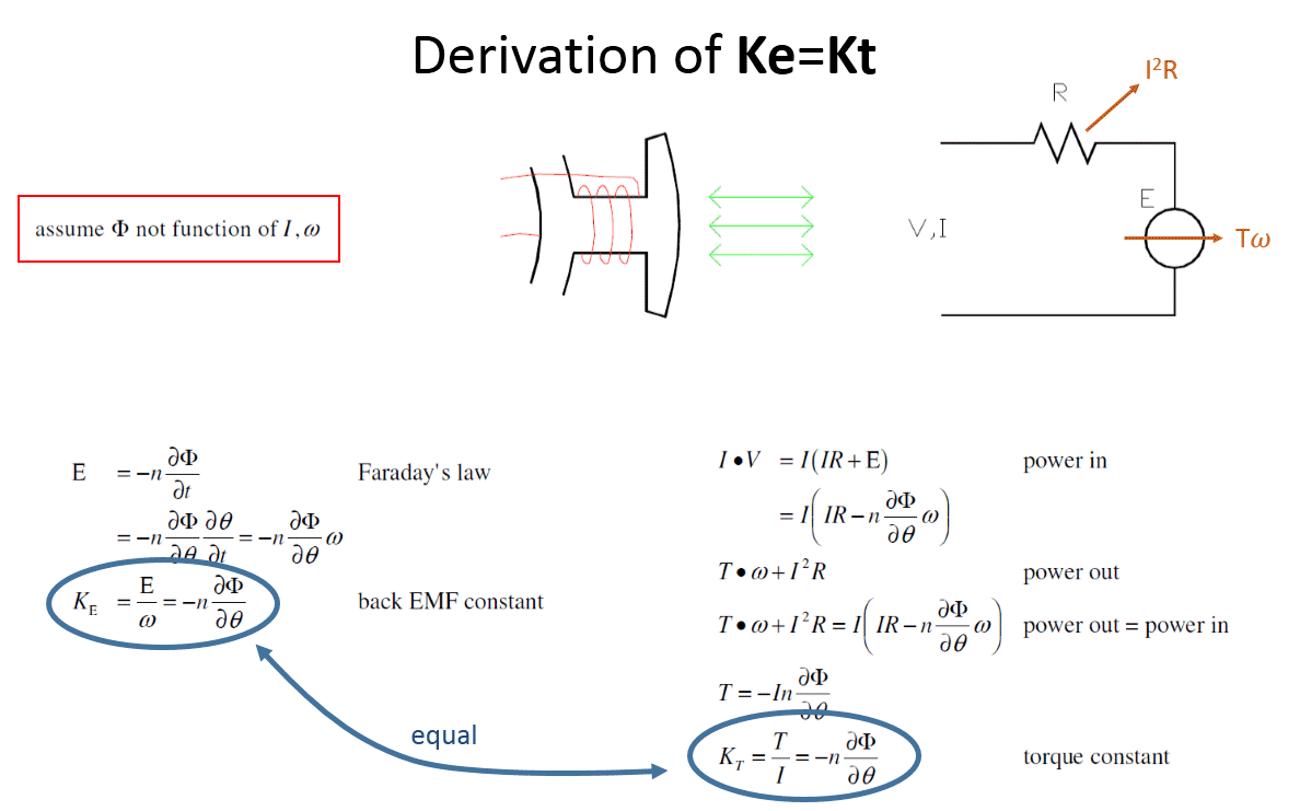
For a motor, we'd like to know how much torque we get when we apply current (T = Kt∙I). A great way to measure (and calculate) the torque constant (Kt) is to spin the motor and measure the generated back emf voltage (V = Ke∙ω). Then apply the well-known identity Kt=Ke.

But be careful. If there is significant steel saturation (due to strong magnets or high currents) this won't work - it will give the wrong answers. The actual identity is δT/δI = -nδΦ/δθ .

kt=ke

Orienting Magnets Properly: Halbach Arrays, SGP

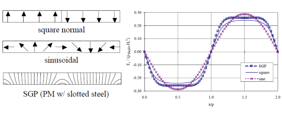
Most permanent magnet devices spray magnetic flux in directions where it is not useful to improving the operation of the machine. Significant performance improvements can be realized by cleverly orienting magnet poles during fabrication. The Halbach array is a well-known example of magnetization pattern manipulation (magnets in air producing one-sided flux).

We've formulated a general method called SGP - Self Generated Pattern that increases performance for a fixed magnet volume. It correctly accounts for nearby permeable materials like steel. We have developed Finite Element methods to synthesize SGP. And it actually works in real life. If this is something that interests you, give us a call.

kt=ke

Understanding BLDC Generators

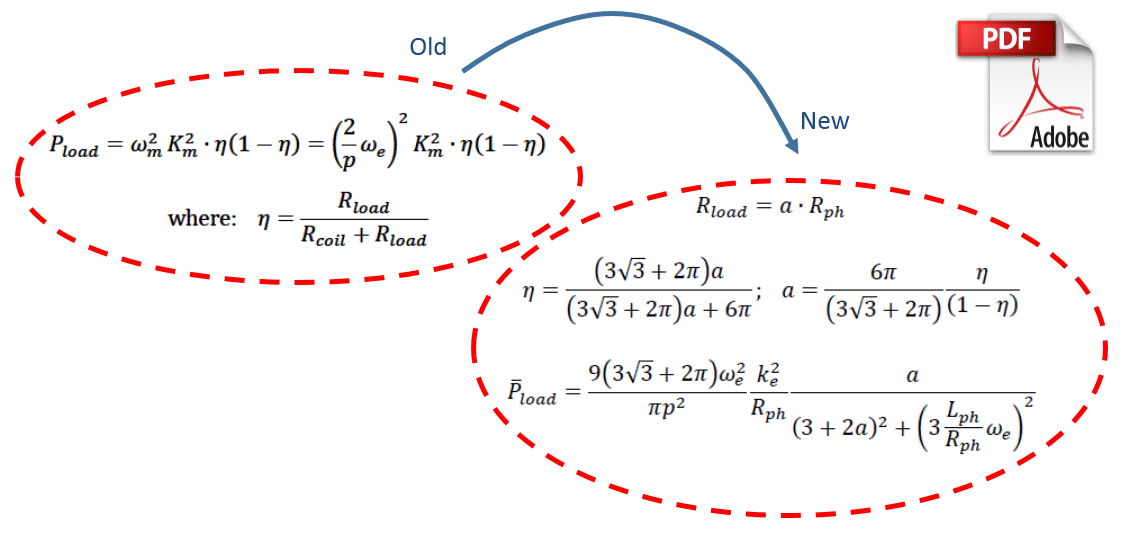
Brushless DC machines make excellent power generators. They are usually designed with simplistic formulas that are the same ones used to design motors. But we've learned after >10 years of designing, prototyping, and testing our generators that you need a much more accurate analytic model to get things right.

Here for the first time we show the formulas we've developed for finite element-based optimization of BLDC generators. Hope you like them.